Brotherhood of Steel Watch
Table of Contents

Ad Victorium!
Intro for muggles
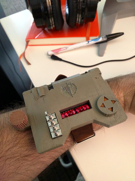
Many people do not like big watches. They are wrong. This “wonderfully ridiculous” watch in my line of large fallout themed watches is called “The Brotherhood of Steel” or the BOS watch. It was born out of various frustrations with its predecessor (the pipman). The project took about two years from start to finish, mostly because I had (have?) no idea what I’m doing. The goal was to build something smaller than the last one (if thinner counts as smaller then mission accomplished), more power friendly (I failed here…somehow) and fully fallout themed as I just really love the world Bethesda created (so please don’t sue me Bethesda).
Thanks to the awesome people in my local hacker group, and the amazing degenerates involved with DEF CON’s #Badgelife community I was able to finish this monster before DEF CON 26. Surprisingly, the project was mentioned on my favorite blog (hackaday) once again. The kind words all of you at con gave were truly humbling, and I am very grateful for them.
The Features:
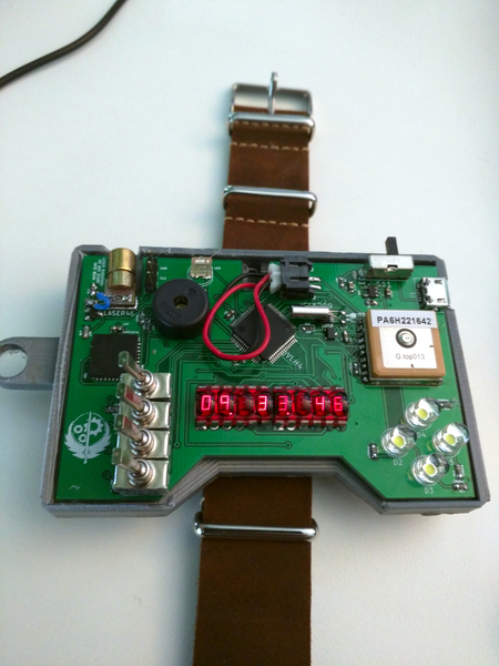
- GPS time syncing (just like the pipman before it
- Tilt compensated compass with LED directional indicators and heading information
- Stop watch / countdown timer
- A Speaker
- Plays the fallout theme (from fallout 4 specifically)
- Geiger Counter sound emulator
- TV B-gone
- A frickn’ laser
- Low power usage (allegedly. The screen sucks down more power than I anticipated)
- Build in USB charger
- A sweet retro look using HP bubble displays manufactured around 1976
- Retro switch controls to emulate the feel of the tech of Fallout
- The ability to repel woman from at least 5 yards
Source code is available on github.
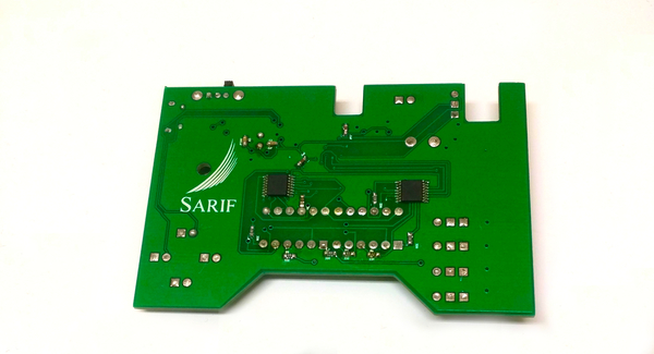
The Back
Operation
Modes of operation:
| Mode | Function |
|---|---|
| 0 | Clock |
| 1 | Compass |
| 2 | Laser/TV remote |
| 3 | GPS |
| 4 | Audio |
| 5 | Stopwatch |
| 6 | Power settings |
Technical stuff for nerds (here be dragons)
Hardware
As mentioned in the video above, the hardware is a mixture of old and new components. The physical switches are meant to invoke the feeling of very early computers, namely the Altair 8800. The displays are retired (and increasingly hard to find) HP QDSP-6064’s. The rest of the parts (which are not visible) and very modern.
The same compass chip from the pipman is used (the HMC6343) as well. The brain of this watch is the NXP kl27z which is a very low power arm processor that runs off C. I used this because spin, the parallax propeller chip’s language from the last watch was pants-on-head retarded. I’m glad I went with this choice, as this particular arm chip is amazing. It has support for just about every communication protocol out of the box, has built in debugging features and contains so many more features that to describe them all would take days to go through (seriously, the manual for this thing is about a thousand pages long). This did create a fair amount of problems however (these will be discussed in the software section).
The first thing I want to mention on the design is that this project was primarily created with the open source marvel, kicad. Part way through development, Eagle cad (the software I was using for the pipman project) pulled a weapons grade stupid move and changed the licensing fee for hobbyists like myself. They wanted users to pay a $60 monthly fee to use their tool. Naturally I drop kicked that software and learned how to use KiCad thanks to these wonderful tutorials. After spending just a days with KiCad, it became obvious that it was light-years ahead of Eagle in almost every way (except for creating curved traces, but I don’t really care about those).
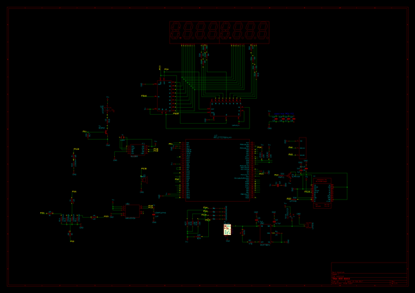
The Schematic created with Kicad
Lessons learned
The most valuable lesson I learned when developing for hardware that was not intended for hobbyist users was to obtain and learn to read an oscilloscope. To those who have never used or seen one before, an oscilloscope is basically a debugging tool for hardware. It literally allows you to see how the parts on your circuit are communicating (or how they are not). As I discovered when trying to write the display driver, you are literally blind to why things are not working. You could spend hours or days trying things at random and seeing what sticks, or you can use this tool and see exactly what is happening and fix it.
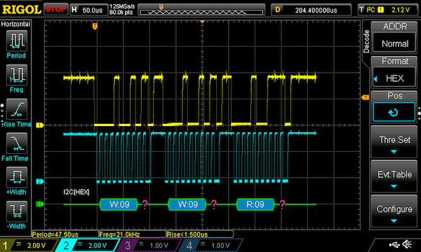
Example scope output when I screwed up the watch’s Real Time Clock
In the example above, I was trying to figure out why the time would not set despite my every effort to do it in code. The clock communicates with a protocol called I2C. I2C works by chaining multiple devices on a single pair of wires. When device A (in this case a clock) needs to be communicated with, I2C requires that the first piece of data you send is the address (a unique identifier that each device on the chain has) so the device knows you are talking to it and not a different peripheral. Turns out I was sending the time setting commands to a device that didn’t exist in the chain (the question marks in the image show there was no reply by the device I was addressing) and the clock itself ignored my commands. I never would have seen this if not for the scope.
Unfortunately for my design, there was no easy way to probe the misbehaving parts without soldering a bunch of wires to the parts themselves. It is because of this I highly recommend putting “debugging ports” over every trace (wire) that has communication signals traveling over it.

Oh look, its on Fire
Another thing I learned this project was how to properly use transistors as switches to turn things like my GPS on & off (properly being the key word here). For the GPS I was using a PNP transistor as a switch. PNPs’ work like this: pull the “switch” (or base) pin low (negative) on the transistor (basically connecting it to ground) and the transistor will allow positive current flow to the part its connected to (the three pins on the transistor in this state would read Positive Negitve Positive).
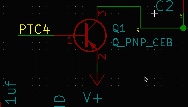
The image above shows how the PNP was originally wired up. Pin 1 (PTC4) was connected to the micro controller, pin 3 to the GPS. Pin 2 was simply connected to power. Pulling pin 1 low did indeed supply power to the GPS, but it had a very catastrophic side effect. Pin 2 and pin 1 at this point were practically connected. Have you ever stuck 2 9v batteries together before? I’ll save you the trouble; they get really, really hot and will pop. The same thing was happening to my micro controller. All the of the power from the battery was suddenly being dumped into a pin that both was not meant to handle that much power, and was directly connected to ground, causing a short. The chip became blistering hot and portions of it became non functional. This issue was solved by placing a 330Ω resistor between pin 1 and the micro controller.
The damage done by this oversight was not discovered until the project was completed. I realized the GPS wasn’t working at all and the entire watch was banjaxed. I had 9 days until DEF Con to get new boards ordered and the project reassembled with no guaranty it would work. Suddenly I had the urge to buy this mug:

Luckily thanks to the light speed performance by JLC PCB, I had new boards in my hand a week later.
Software
This project runs on:
- C
- Kinetis SDK
- Blood magic (probably)
The Kinetis SDK is a beast, and if you have never used it or anything like it before, you are going to have a rough time. The documentation provided by NXP for the most part lists what functions the SDK has, not so much how or where to use them. I plan on writing a more in depth article on how to use the SDK in the near future from a beginner’s point of view. To sum up what that article will contain:
- Read the example code provided
- Read the example code provided again
- be sure to understand how to pin “muxing” works
- If things do not work, the only documentation on the functions is the SDK itself. If you are using FunctionX and its not working, grep the SDK source code to find its definition.
grep -R "FunctionX" .- Often the SDK itself has tons of comments in the code that explain exactly what something does and how it works
- Not all pins on the microprocessor can do all things (unlike a propeller). Make sure the pin you intend to use as a UART, I2C or the SPI protocol supports that operation (that mistake cost me a few boards).
Eventually you will have something that compiles and works.
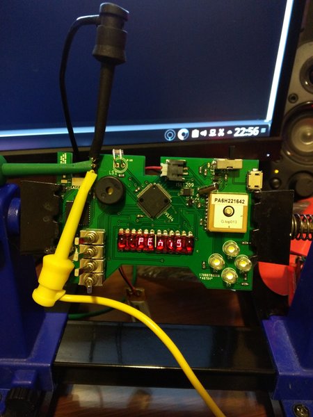
Hello World! but for 4 year olds
Music
The music for the fallout theme really was a joy to program. I myself have zero musical talent and cannot read sheet music. These handicaps however proved not to be a challenge at all thanks to the resources I will mention below. First it is important to understand how the music is generated. The speaker used was a simple buzzer. To play a tone, power must be applied the buzzer, and quickly shutoff. The faster you do this, the higher the tone that is played. The Kinetis SDK has modules that will do this for you (PWM functionality), provided you supply a target frequency. Thankfully, someone somewhere was able to map every common piano key note to a frequencey. Now that I had a “Rosetta stone” to translate for me, finding Fallout music was fairly easy.
Bad make files & SDK hacking
The most complicated software problem I ran across creating this watch was getting the UART (reading the GPS data) working. Typically I find UART to be the easiest communication protocol to use in embedded programming. But whenever I ran the code, the MCU (micro controller unit) would sit and wait forever for the communication to happen…even though it was happening at least once a second. I had poured over all the documentation and examples I could find. All of them confirmed what I was doing was correct.
uart_state_t g_uartState;

static const gpio_input_pin_user_config_t SatFix={
    .pinName=GPIO_MAKE_PIN(GPIOC_IDX,10) //setting up pin PTC10 as the GPS Reader
};

uart_user_config_t g_uartConfig= {
    .baudRate = 9600u,
    .parityMode = kUartParityDisabled,
    .stopBitCount = kUartOneStopBit,
    .bitCountPerChar = kUart8BitsPerChar,
};

uint8_t ReadChar()
{
    uint8_t rxChar;
    UART_DRV_ReceiveDataBlocking(2u, &rxChar, 1u,1000u); //Read UART2 (on PTC10), 1 character at a time
    return rxChar;
} arm-none-eabi-objdump -d debug/BOS.elf | less000008c6 <UART2_FLEXIO_IRQHandler>:
8c6: b510 push {r4, lr}
8c8: 2002 movs r0, #2
8ca: f003 fb3f bl 3f4c <FLEXIO_IRQHandler>
8ce: bd10 pop {r4, pc}I had been using the badges make files to build the project because I’m lazy and didn’t want to set it up myself. My project was not using a feature called FLEXIO that Amatus’s project was using. Altering my cmake list file was the solution.
"${ProjDirPath}/KSDK_1.2.0/platform/drivers/src/dma/fsl_dma_irq.c"
"${ProjDirPath}/KSDK_1.2.0/platform/drivers/src/lptmr/fsl_lptmr_irq.c"
"${ProjDirPath}/KSDK_1.2.0/platform/drivers/src/flexio/fsl_flexio_irq.c"//removed this bastard right here
"${ProjDirPath}/KSDK_1.2.0/platform/drivers/src/uart/fsl_uart_irq.c" //Added this
"${ProjDirPath}/KSDK_1.2.0/platform/drivers/src/spi/fsl_spi_irq.c"
"${ProjDirPath}/KSDK_1.2.0/platform/drivers/src/i2c/fsl_i2c_irq.c"
What was happening was this: the UART runs off of interupts. Including the unused FLEXIO IRQ file was somehow setting the UART to listen for a flex io interrupt to alert it to incoming data. Since Flex IO was not used in the project, my program would wait forever. Removing the flex io IRQ file and adding the correct one for UART corrected the bug.
Here is the corrected output
000008c6 <UART2_FLEXIO_IRQHandler>:
     8c6:       b510            push    {r4, lr}
     8c8:       2002            movs    r0, #2
     8ca:       f003 fb3f       bl      3f4c <UART_DRV_IRQHandler>
     8ce:       bd10            pop     {r4, pc}
Alright, now that that horribly confusing issue was fixed, maybe I could finally test my GPS parsing code! Nope. the program still hung when run. At this point I was ready to give up and start a quiet life as a farmer someplace remote. Following the advice given above by digging through the source code of the SDK, we found a bug in their software. The UART IRQ handler was only getting called for specific MCU models. Mine, the KL27 was not in the list of MCUs the code enabled that interrupt for. Adding it here did the trick.
#elif defined (KL27Z4_SERIES) || defined (KL27Z644_SERIES) || defined (KL17Z644_SERIES) ||  defined (KL43Z4_SERIES)

#if (UART_INSTANCE_COUNT > 0)
/* Implementation of UART1 handler named in startup code. */
void UART2_FLEXIO_IRQHandler(void)
{
    UART_DRV_IRQHandler(2);
}
#endif
And just like that, my GPS parsing code worked beautifully. Once I learned how interrupts worked, suddenly much of the black magic used to run this software began to make sense to me. Interrupts are actually really neat once you learn how to use them.
Case
The last time I made a custom enclosure for a project I used Blender. Suddenly realizing that I’m not a masochist I quickly abandoned it in favor of OpenScad. Why OpenScad? Blender was created for art like video games or movies. Trying to do anything with any kind of precision was as pleasant as using a chainsaw as a bicycle seat. You want to make a hole 3.5 mm tall and 5 mm wide? In blender you’d have to make the hole, measure it, see you where 10 mm off, resize it, measure it and check it again until it was either close enough or you had downed too many bottles of booze in the process and just gave up.
OpenScad however was built for precise modeling. Unlike blender you do not draw anything. OpenScad is all code.
cube([125,225,140]);That command creates a 125x225 cube that is 140mm high. That’s it. No more checking to ensure its the right size. Armed with a pair of calipers, I was able to create this rather quickly.
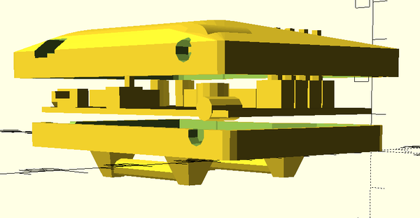
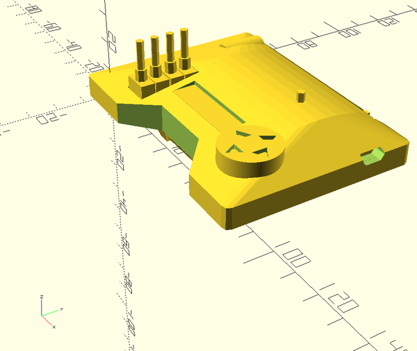
An ealy version without logos or thumb screws
The watch band is from Amazon.
And that’s about it. If you stuck around to end, thanks for reading.
