Project Nakatomi
Table of Contents
                                   &&             #&.
                                  &&&&             #&&&&
                               &&&&&&&      &/     #&&&&&&
                             &&&&&&&&&   ,&&&&&&   %&&&&&&&&&
                            &&&&&&&&&  &&&&&&&&&&&.  &&&&&&&&#
                        %&&&  &&&&   &&&&&&(,*&&&&&&&  %&&&  #&&&
                      &&&&&&&&/   &&&&&,   &&&&   &&&&&    &&&&&&&&/
                       &&&&&&&&&&&&&&&     &&&%    &&&&&&&&&&&&&&&(
                         /&&&&&&&&&&&&  &&&& &&&&& #&&&&&&&&&&&&
                        &&  &&&&&&&&#    &&   %&&    &&&&&&&&/ ,&(
                      &&&&&&  *&&&                     %&&&  &&&&&&&
                        &&&&&&&  *&&&               ,&&&  ,&&&&&&
                          ,&&&&&&&&                    &&&&&&&&
                             &&&                         %&&
History
Last Christmas while spending time antiquing with family, I stumbled upon the remains of an ancient radio. Excited to get my hands on some tube tech, I was immediately drawn to it. Unfortunately for me, this particular radio was nothing more than a barren shell. This however created the idea to “refurbish” the radio with a Raspberry Pi and make a more modern stereo out of it without feeling guilt for destroying tubes.
The radio itself is a 1940s Philco Skyscraper™. Since I’m a sucker for terrible puns, project Nakatomi was born.
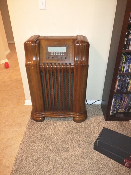
The original radio.
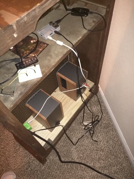
Putting the speakers in.
Hardware
The project uses:
- Edifer bookshelf speakers
- A Rasbery Pi2
- An Arduino
- RGB LCD
A Raspberry Pi project itself is hardly interesting these days. Likewise, a Pi running mpd is hardly worth writing a blog post about. However, this project ran into some technical hurdles that are worth some discussion.
The Edifer speakers presented an interesting opportunity. Originally I just wanted a cheap set of speakers to plug the system into. These speakers however, come with the ability to pair Bluetooth devices. It would be nice to allow guests (assuming I ever get anymore. Thanks Covid) to pair to the radio and play whatever they like. Unfortunately the speakers can only switch to Bluetooth mode by pressing a button on the included remote control, or by pressing a button on the speakers themselves. Neither option was a good one for this project (the speakers themselves would not be easy to get to for the button press, and the remote control signal couldn’t be seen by the speakers if it was broadcast outside the radio case). Hitting buttons on a remote is also a super lame way to switch audio sources as it takes away the feeling of the radio being one complete unit. Ideally, there would be a knob or something on the face plate to activate this mode.
This presented a technical challenge, as the only choices to achieve this goal would be to either A) cut into the speakers themselves and solder wires onto the button leads (which would damage those fine speaker cases), or B) reverse engineer the IR protocol the remote control used and create a remote control from the Pi (a lot of work). I decided on option B.
NEC Protocol
The first thing I did was get a cheap IR sensor (I think this one is from Adafruit) and hooked it into my oscilloscope to view the signal.
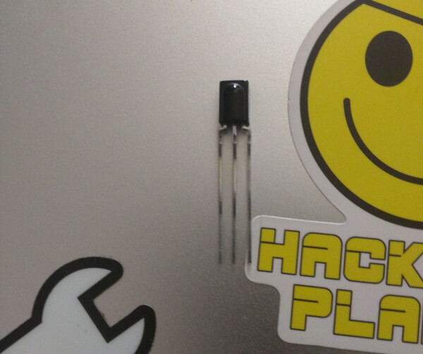
IR sensor.
This is what I saw:
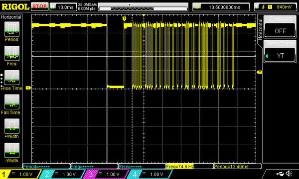
Output from Edifer remote.
It turns out that most IR devices like the Edifer remote use a protocol called NEC. Thankfully this protocol is amazing documented. As clearly I am not the first person to try to create my own NEC remote control, the heavy lifting in understanding and manipulating the protocol is already out there. Dave from the EEV Blog did an amazing video on how the protocol works, and even wrote his own Arduino code to emulate it. If you really want to get down into the nitty gritty details of NEC, I really recommend watching Dave’s video.
The protocol basically works like this: longer IR pulses are ones, shorter ones are zeros.

The above image is slightly off, as the first two bytes are the address itself, not the device address+inverse. What appear to be solid blocks in the diagram above are actually extremely fast pulses of IR light (13 micro seconds between each pulse). This is shown below:
The codes for the Edifer speakers are as follows:
Blutooth:
00001000 11100111 01110000 10001111

line 1:
00001000 11100111 01010000 10101111

line 2:
00001000 11100111 10101000 01010111
My goal was to port Dave’s code the Pi, attach an IR LED to it, and attach a knob so when I turned it the proper IR codes would fire. This did not take too long.
Testing
Surprise, nothing worked. When I connected the pi to my oscilloscope, I could see the problem; I was getting 30 micro second delays, not 13 as I had coded. The Pi itself is a much more powerful system than an Arduino, so why was the timing so off, and why by so much?
The Pi
There is a reason these things have shields (daughter board accessories).
This quote is from the guy who wrote IR slinger (a library meant to solve this issue):
And even a compiled program written in C or C++ could be interrupted by the operating system, as your program is not the only thing running and the OS will stop your program to give other programs a chance to run.
His solution:
but it [IR slinger] uses something like a “kernel module” or “kernel extension” that runs at the same level as the operating system.
So I wrote new code for the Pi that made use of IR slinger. Even with IR slinger my timing was still off by about 5 micro seconds. I quickly abandoned the idea of having The Pi control my IR LED.
Arduino
I ended up using an Arduino to drive the IR LED. The Arduino is tied to the Pi itself, so I can still control the Edifer speakers from the Pi indirectly. I ended up using Dave’s code almost verbatim. The changes were in the timing (Arduino Nano vs Uno) and adding listener code to check for the Pi’s triggering event:
    digitalWrite(IRLEDpin, HIGH);   //turn on the IR LED
    delayMicroseconds(10);          //delay for 10us (9us + digitalWrite)
    digitalWrite(IRLEDpin, LOW);    //turn off the IR LED
    delayMicroseconds(10);          //delay for 10us (9us + digitalWrite)
Dave’s original code can be found here, and a copy of my version is here.
Here is the initial test video I made for the NEC work. By plugging the Arduino into a power supply, you can see the speaker LED change from green to blue as the speaker changes sources.
The Daemon
Not much to talk about here for the software. It’s coded in C++ (because apparently I hate myself. Python would have been easier), uses pigpio and libmpdclient. I wrote the display driver myself. It is a standard HD44780 display. If you ever find yourself needing to write your own driver for one of these, this handy emulator is a must-have.
The source code is located here.
3d Printering
The knob cover is actually a replica Philco knob I found off Thingiverse.
The rest of the panel was designed using OpenSCAD.
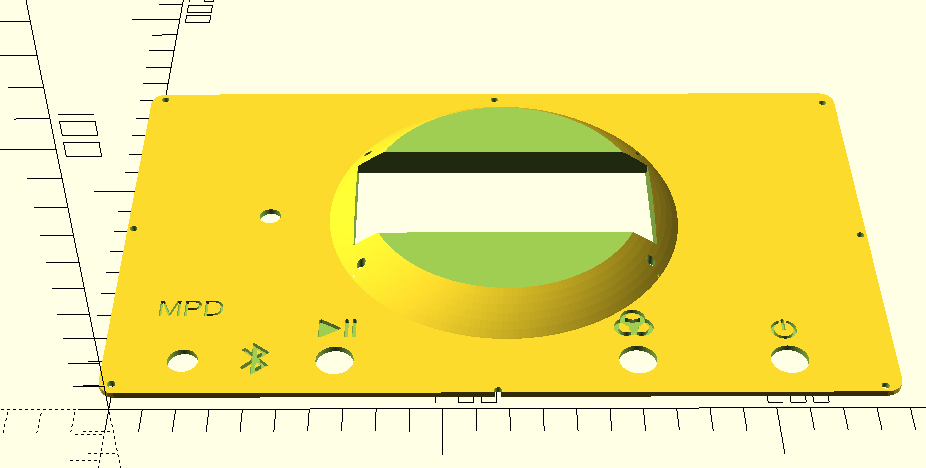
The faceplate is published on github.
